
Assignment 4
Circuit Specification
The following truth table describes the behavior of an exactly two detector circuit with four inputs (A, B, C, and D) and one output (E). If exactly two of the inputs are 1, then this circuit should output a 1. Otherwise, it should output a 0.
| A | B | C | D | E | |
|---|---|---|---|---|---|
| 0 | 0 | 0 | 0 | 0 | |
| 0 | 0 | 0 | 1 | 0 | |
| 0 | 0 | 1 | 0 | 0 | |
| 0 | 0 | 1 | 1 | 1 | |
| 0 | 1 | 0 | 0 | 0 | |
| 0 | 1 | 0 | 1 | 1 | |
| 0 | 1 | 1 | 0 | 1 | |
| 0 | 1 | 1 | 1 | 0 | |
| 1 | 0 | 0 | 0 | 0 | |
| 1 | 0 | 0 | 1 | 1 | |
| 1 | 0 | 1 | 0 | 1 | |
| 1 | 0 | 1 | 1 | 0 | |
| 1 | 1 | 0 | 0 | 1 | |
| 1 | 1 | 0 | 1 | 0 | |
| 1 | 1 | 1 | 0 | 0 | |
| 1 | 1 | 1 | 1 | 0 |
Assignment
Design a circuit that has the above truth table. Then, implement your design in Logisim and test it with a test vector containing the entire truth table.
Hint
I suggest starting by working out the boolean algebra symbols for the truth table’s sum-of-products like we did in class. Then, draw the circuit that corresponds to your sum-of-products using one stage of ANDs and another of ORs. You do not have to get the circuit in its most simple form - anything that has this truth table will work.
Grading
This is a 4-point assignment. See the rubric from the syllabus.
What to turn in
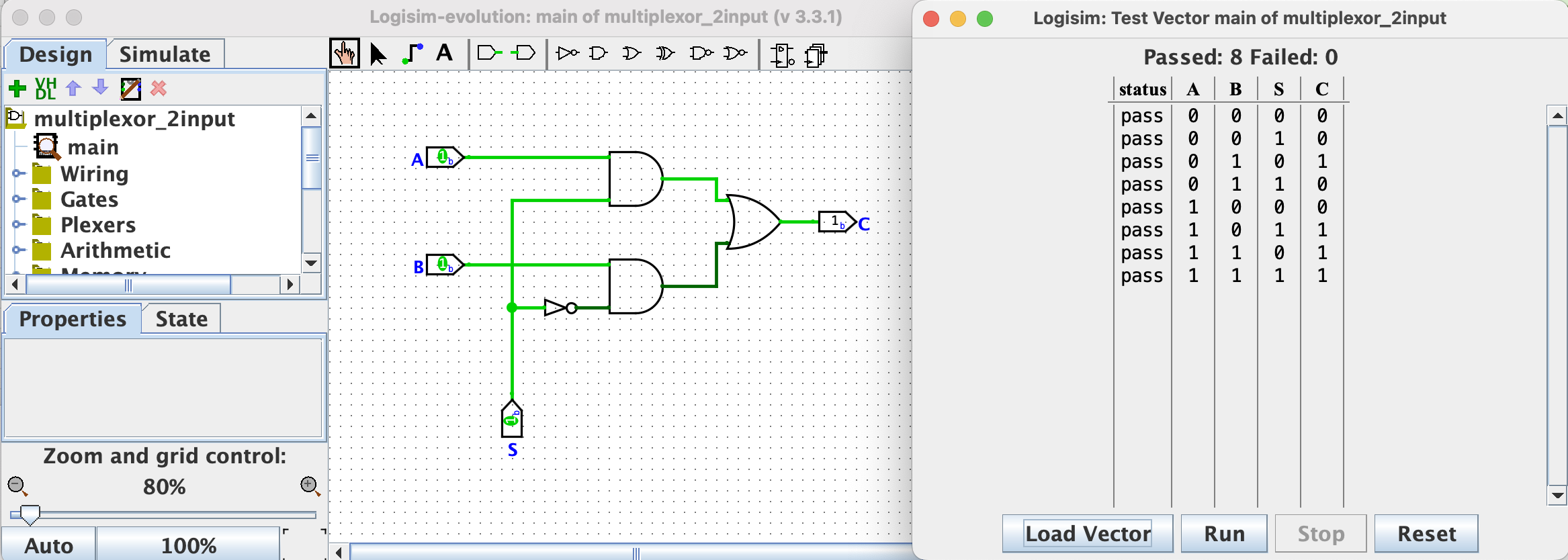
Take a screenshot of your Logisim circuit and the test vector window showing the pass/fail status of the circuit for every input from the truth table. Your screenshot should look something like this (except this is a different circuit than the one you will make for the assignment):
Where to turn it in
Submit your screenshot image file to the Assignment 4 hand-in form on Blackboard.