## Logic Gates and Truth Tables --- CS 130 // 2024-09-24 <!--=====================================================================--> ## Reminder * Exam 1 is up and is due by the end of the day on Thursday * Make sure to read the instructions * We will not meet for class on Thursday * I will be here if you want to come and work on the exam or Assignment 4 <!--=====================================================================--> ## Vermeer Digital Bulldogs https://www.drake.edu/cs/internships/vermeerdigitalbulldogs/ Deadline is October 15th <!--=====================================================================--> # Finishing up Procedures <!-- .slide: data-background="#004477" --> <!--====================================================================--> ## Stack Frames 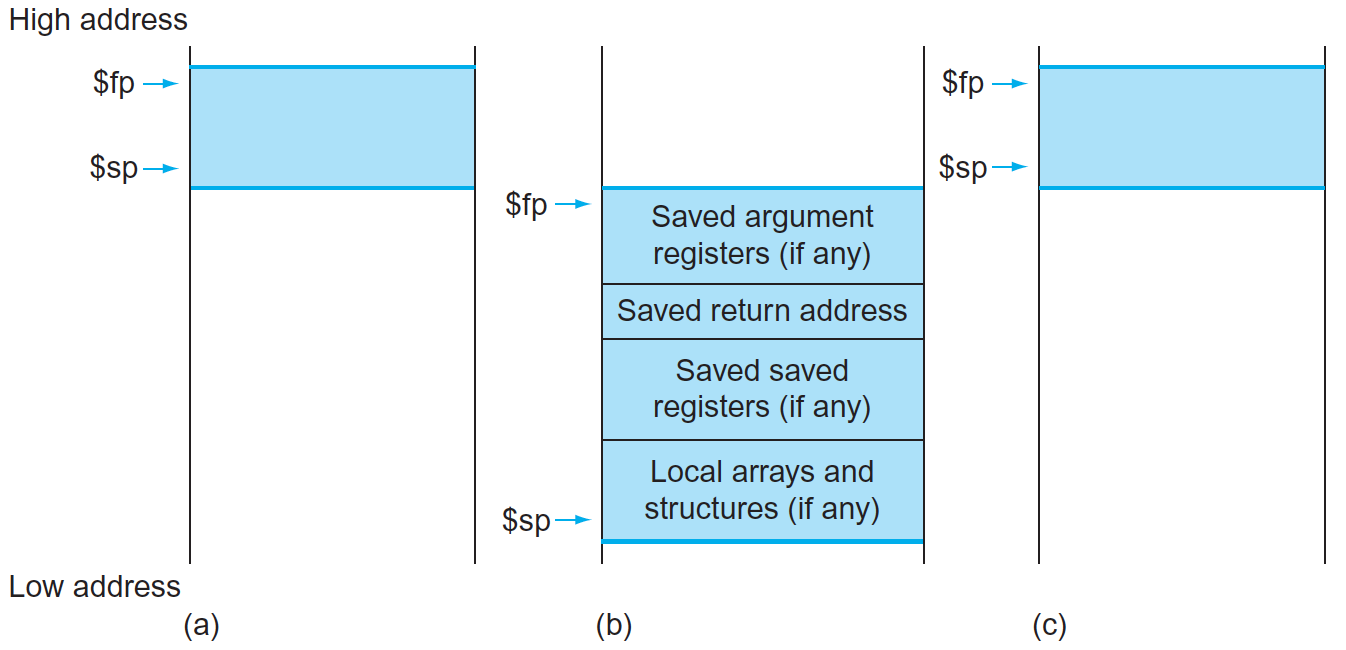 <!--====================================================================--> ## Exercise from last time - Convert the following C code into MIPS ```python def double_it(e): return e + e def calc(c): d = double_it(7) return c + d def main(): a = 5 b = calc(a) ``` <!----------------------------------> ## Exercise Solution: Compute ```python def double_it(e): return e + e ``` ```mips double_it: add $v0, $a0, $a0 # returns e + e jr $ra ``` <!-- .element: class="fragment"--> <!----------------------------------> ## Exercise Solution: Calc - Take 1 ```python def calc(c): d = double_it(7) return c + d ``` ```mips calc: li $a0, 7 # puts 7 in a0 jal double_it # calls compute(7) add $v0, $v0, $a0 # adds argument to result jr $ra ``` <!-- .element: class="fragment"--> - <!-- .element: class="fragment"--> Unfortunately this will fail. Why? + <!-- .element: class="fragment"--> Both `$a0` and `$ra` will be erased! <!----------------------------------> ## Exercise Solution: Calc - Take 2 ```python def calc(c): d = double_it(7) return c + d ``` ```mips calc: addi $sp, $sp, -8 # allocates space sw $a0, 0($sp) # stores c on the stack sw $ra, 4($sp) # stores $ra on the stack li $a0, 7 # puts 7 in a0 jal double_it # calls double_it(7) lw $ra, 4($sp) # restores $ra lw $a0, 0($sp) # restores argument addi $sp, $sp, 8 # deallocates space add $v0, $v0, $a0 # adds argument to result jr $ra ``` <!-- .element: class="fragment"--> <!----------------------------------> ## Exercise Solution: Main ```python def main(): a = 5 b = calc(a) ``` ```mips main: li $s0, 5 # a = 5 move $a0, $s0 # loads a into argument jal calc # calls calc(5) move $s1, $v0 # b = result ``` <!-- .element: class="fragment"--> <!--====================================================================--> ## Assignment - [Assignment 4](../../assignments/assignment-4/) - Translate a Python program that has functions and Arrays - 8 points - Part of it has been done - you'll do a "middle" function. <!--=====================================================================--> ### Preparing for part 2 of the course We will soon be using a digital logic simulator called Logisim-Evolution * [Information here](https://github.com/logisim-evolution/logisim-evolution) * [Download here](https://github.com/logisim-evolution/logisim-evolution/releases/tag/v3.7.2) - make sure to get v3.7.2 - **jar** file: should work for anyone (similar to MARS) - **msi** file: installer for Windows (you probably want x86 version) - **dmg** file: installer for Mac (may or may not work for M1/M2/M3 Macs) <!--=====================================================================--> # Course Themes <!-- .slide: data-background="#004477" --> <!--=====================================================================--> ## Overarching Theme - Learning how a high-level program is actually executed on your computer's processor <!----------------------------------> 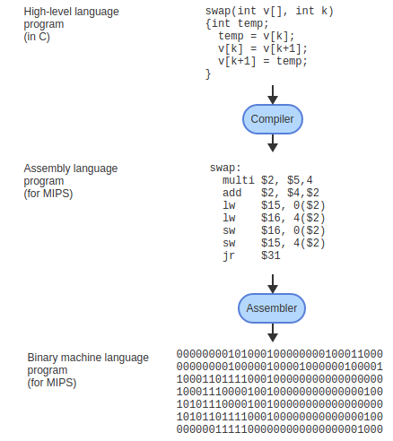 <!----------------------------------> ## Trajectory of the Course 1. Assembly language programming 2. **Digital logic** 3. Processor architecture 4. The C Programming Language <!--=====================================================================--> ## Basic CPU Operations - Recall that most operations operate on one or more 32-bit registers + <!-- .element: class="fragment"--> `add $s0,` `$s1`, `$s2` takes two 32-bit numbers, adds them up, and produces a new 32-bit number - <!-- .element: class="fragment"--> How can we build a machine that takes 0s and 1s as input and produces 0s and 1s as output? <!--=====================================================================--> # Digital Logic <!-- .slide: data-background="#004477" --> NOTE: Discuss how hard electrical engineering is and why it is so useful to focus on the simplicity of digital logic <!--=====================================================================--> ## Transistors - CPU instructions are implemented with nanoscale switches called **transistors** <div class="twocolumn"> <div> 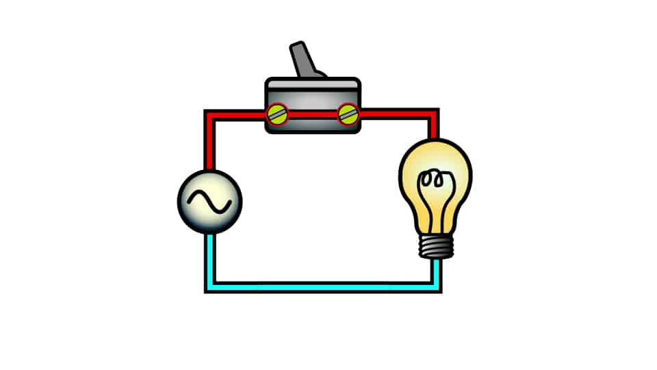 <!-- .element: class="fragment"--> </div> <div> You can think of a transistor as a "switch" with states "on" and "off" <!-- .element: class="fragment"--> </div> </div> <!----------------------------------> ## Digital Logic - Learning about electricity, capacitors, resistors, is beyond the scope of this course - <!-- .element: class="fragment"--> For now, it is useful to abstract away the details of electrical engineering - <!-- .element: class="fragment"--> We will think about circuits in terms of 0s and 1s going through the wires of a circuit <!----------------------------------> ## Input/Output as Voltages <div class="twocolumn"> <div> - The 0s and 1s of our circuits will be "low" and "high" voltages across a wire, similar to a light bulb being "on" and "off" </div> <div> 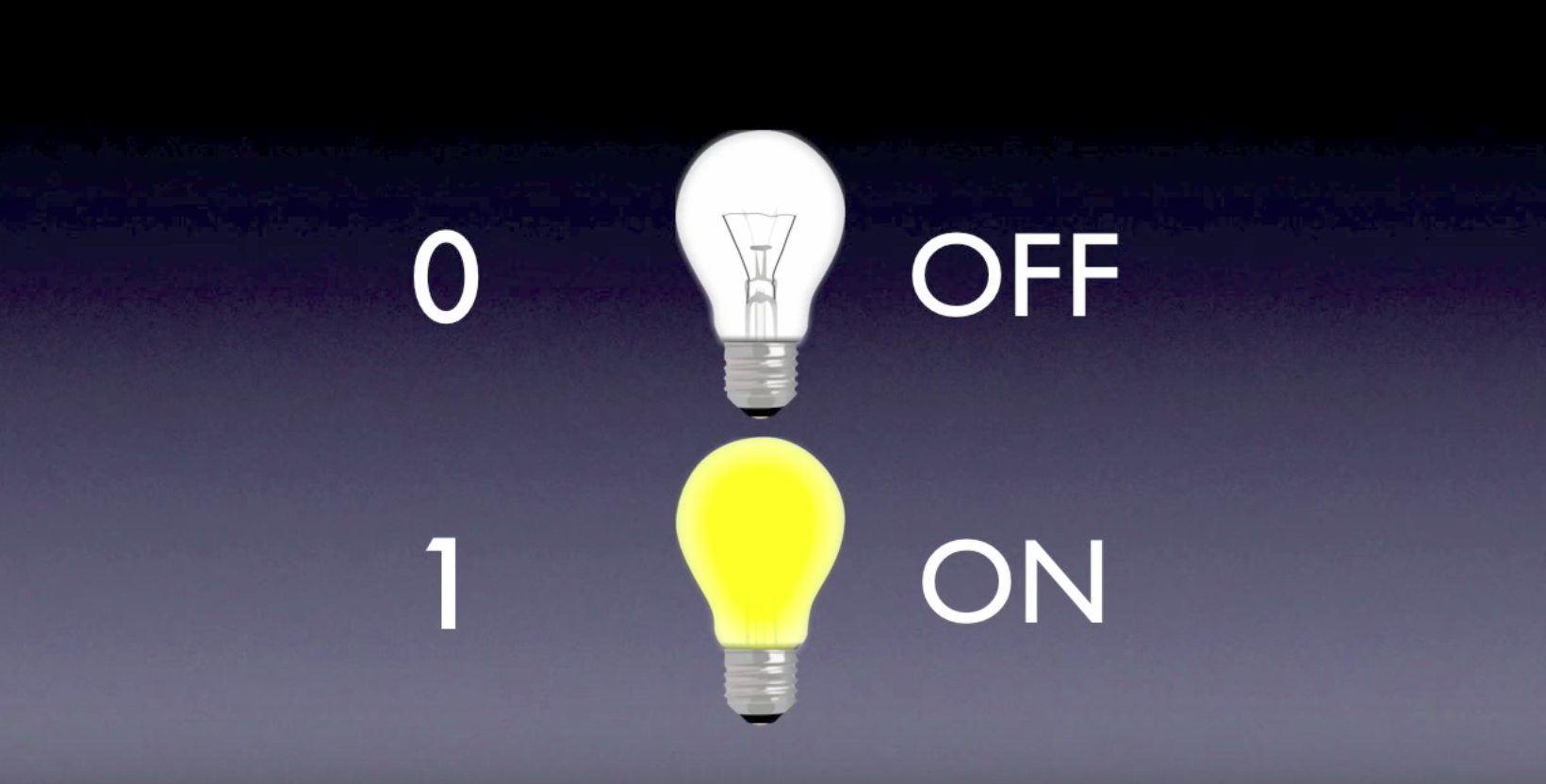 </div> </div> <!--=====================================================================--> ## Logic Gates - A **logic gate** is an elementary circuit that takes one or more bits as input and produces one or more bits as output - <!-- .element: class="fragment"--> Many of these logic gates can be constructed with one or two transistors <!----------------------------------> ## AND Gate <table> <tbody> <tr> <td>Input 1</td> <td>Input 2</td> <td>Output</td> </tr> <tr> <td>0</td> <td>0</td> <td>0</td> </tr> <tr> <td>0</td> <td>1</td> <td>0</td> </tr> <tr> <td>1</td> <td>0</td> <td>0</td> </tr> <tr> <td>1</td> <td>1</td> <td>1</td> </tr> </tbody> </table> 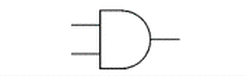 <!----------------------------------> ## OR Gate <table> <tbody> <tr> <td>Input 1</td> <td>Input 2</td> <td>Output</td> </tr> <tr> <td>0</td> <td>0</td> <td>0</td> </tr> <tr> <td>0</td> <td>1</td> <td>1</td> </tr> <tr> <td>1</td> <td>0</td> <td>1</td> </tr> <tr> <td>1</td> <td>1</td> <td>1</td> </tr> </tbody> </table> 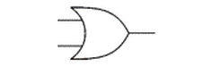 <!----------------------------------> ## NOT Gate <table> <tbody> <tr> <td>Input</td> <td>Output</td> </tr> <tr> <td>0</td> <td>1</td> </tr> <tr> <td>1</td> <td>0</td> </tr> </tbody> </table> 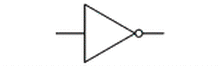 <!----------------------------------> ## NAND Gate <table> <tbody> <tr> <td>Input 1</td> <td>Input 2</td> <td>Output</td> </tr> <tr> <td>0</td> <td>0</td> <td>1</td> </tr> <tr> <td>0</td> <td>1</td> <td>1</td> </tr> <tr> <td>1</td> <td>0</td> <td>1</td> </tr> <tr> <td>1</td> <td>1</td> <td>0</td> </tr> </tbody> </table> 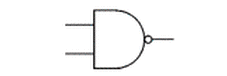 <!----------------------------------> ## NOR Gate <table> <tbody> <tr> <td>Input 1</td> <td>Input 2</td> <td>Output</td> </tr> <tr> <td>0</td> <td>0</td> <td>1</td> </tr> <tr> <td>0</td> <td>1</td> <td>0</td> </tr> <tr> <td>1</td> <td>0</td> <td>0</td> </tr> <tr> <td>1</td> <td>1</td> <td>0</td> </tr> </tbody> </table> 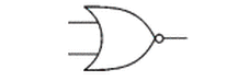 <!----------------------------------> ## XOR Gate <table> <tbody> <tr> <td>Input 1</td> <td>Input 2</td> <td>Output</td> </tr> <tr> <td>0</td> <td>0</td> <td>0</td> </tr> <tr> <td>0</td> <td>1</td> <td>1</td> </tr> <tr> <td>1</td> <td>0</td> <td>1</td> </tr> <tr> <td>1</td> <td>1</td> <td>0</td> </tr> </tbody> </table> 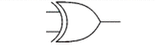 (exclusive OR) <!--=====================================================================--> ### Demo: What is the truth table for the following circuit? --- <div class="twocolumn" style="font-size: 70%"> <div> 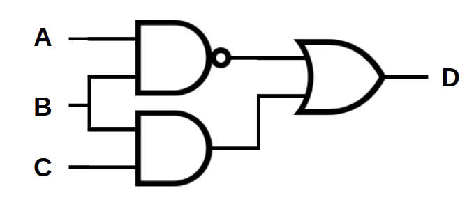 </div> <div> <table> <tbody> <tr> <td>A</td> <td>B</td> <td>C</td> <td><b>D</b></td> </tr> <tr> <td>0</td> <td>0</td> <td>0</td> <td> </td> </tr> <tr> <td>0</td> <td>0</td> <td>1</td> <td> </td> </tr> <tr> <td>0</td> <td>1</td> <td>0</td> <td> </td> </tr> <tr> <td>0</td> <td>1</td> <td>1</td> <td> </td> </tr> <tr> <td>1</td> <td>0</td> <td>0</td> <td> </td> </tr> <tr> <td>1</td> <td>0</td> <td>1</td> <td> </td> </tr> <tr> <td>1</td> <td>1</td> <td>0</td> <td> </td> </tr> <tr> <td>1</td> <td>1</td> <td>1</td> <td> </td> </tr> </tbody> </table> </div> </div> <!--=====================================================================--> #### Exercise 1. Fill out the truth table 2. Describe what the circuit does using words <div class="twocolumn" style="font-size: 70%"> <div> 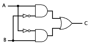 </div> <div> <table> <tbody> <tr> <td>A</td> <td>B</td> <td><b>C</b></td> </tr> <tr> <td>0</td> <td>0</td> <td> </td> </tr> <tr> <td>0</td> <td>1</td> <td> </td> </tr> <tr> <td>1</td> <td>0</td> <td> </td> </tr> <tr> <td>1</td> <td>1</td> <td> </td> </tr> </tbody> </table> </div> </div> *NB:* a filled dot where wires cross means that the wire splits. If no dot appears, it means one wire is routed over the top of the other. <!--=====================================================================--> ### Symbolically describing a circuit <div class="twocolumn" style="font-size: 70%"> <div>  </div> <div> $$D = \overline{(A\cdot B)} + (B \cdot C)$$ </div> </div> - $\overline{A}$ "not $A$" - $\cdot$ "and" - $+$ "or" <!--=====================================================================--> ### Exercise Symbolically describe the circuit  <!--=====================================================================--> ### Exercise 1. Draw a circuit representing the logic symbols 2. Write the truth table for the circuit $$ C = (A \cdot \overline{S}) + (B \cdot S) $$ <!--=====================================================================--> ### Challenge Exercise <div class="twocolumn" style="font-size: 70%"> <div> Can you come up with a circuit that has this truth table? - A, B, and C are inputs - E is an output Verbally describe what this circuit does. Write the logic symbols representing this circuit. </div> <div> <table> <tbody> <tr> <td>A</td> <td>B</td> <td>C</td> <td><b>E</b></td> </tr> <tr> <td>0</td> <td>0</td> <td>0</td> <td><b>0</b></td> </tr> <tr> <td>0</td> <td>0</td> <td>1</td> <td><b>1</b></td> </tr> <tr> <td>0</td> <td>1</td> <td>0</td> <td><b>1</b></td> </tr> <tr> <td>0</td> <td>1</td> <td>1</td> <td><b>0</b></td> </tr> <tr> <td>1</td> <td>0</td> <td>0</td> <td><b>1</b></td> </tr> <tr> <td>1</td> <td>0</td> <td>1</td> <td><b>0</b></td> </tr> <tr> <td>1</td> <td>1</td> <td>0</td> <td><b>0</b></td> </tr> <tr> <td>1</td> <td>1</td> <td>1</td> <td><b>1</b></td> </tr> </tbody> </table> </div> </div>