
Assignment 5
Circuit Specification
The following truth table describes the behavior of a three-or-more detector circuit with four inputs (A, B, C, and D) and one output (E). If three or more of the inputs are 1, then this circuit should output a 1. Otherwise, it should output a 0.
| A | B | C | D | E | |
|---|---|---|---|---|---|
| 0 | 0 | 0 | 0 | 0 | |
| 0 | 0 | 0 | 1 | 0 | |
| 0 | 0 | 1 | 0 | 0 | |
| 0 | 0 | 1 | 1 | 0 | |
| 0 | 1 | 0 | 0 | 0 | |
| 0 | 1 | 0 | 1 | 0 | |
| 0 | 1 | 1 | 0 | 0 | |
| 0 | 1 | 1 | 1 | 1 | |
| 1 | 0 | 0 | 0 | 0 | |
| 1 | 0 | 0 | 1 | 0 | |
| 1 | 0 | 1 | 0 | 0 | |
| 1 | 0 | 1 | 1 | 1 | |
| 1 | 1 | 0 | 0 | 0 | |
| 1 | 1 | 0 | 1 | 1 | |
| 1 | 1 | 1 | 0 | 1 | |
| 1 | 1 | 1 | 1 | 1 |
Assignment
Design a circuit that has the above truth table. Then, implement your design in Logisim and test it with a test vector containing the entire truth table.
Hint
I suggest starting by working out the boolean algebra symbols for the truth table’s sum-of-products like we did in class. Then, draw the circuit that corresponds to your sum-of-products using one stage of ANDs and another of ORs. You do not have to get the circuit in its most simple form - anything that has this truth table will work.
Grading
This is a 4-point assignment. See the rubric from the syllabus.
What to turn in
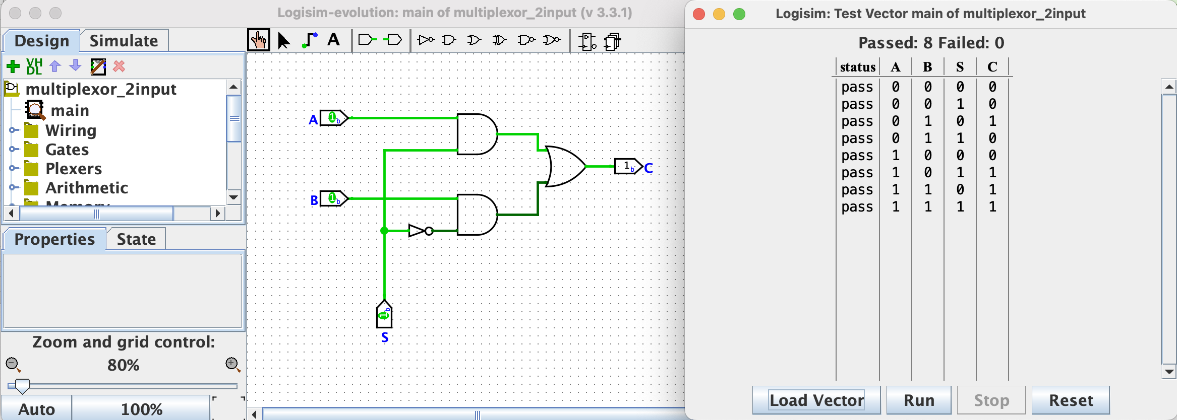
Take a screenshot of your Logisim circuit and the test vector window showing the pass/fail status of the circuit for every input from the truth table. Your screenshot should look something like this (except this is a different circuit than the one you will make for the assignment):
Where to turn it in
Submit your screenshot image file to the Assignment 5 hand-in form on Blackboard.